
Experts in air filtration
Project FL – CleanPULSE CPCF Ceramic Filters for a Pilot Plant in Denmark
We were first approached by a minerals processing supplier to the global mining industry in 2023 to quote for 2 high temperature filters for a future pilot plant as the company works towards its goal of providing solutions for net zero-emissions mining by 2030.
After extensive interaction with the technical team based in India and revisions to the requirement specification, which is not uncommon for a pilot plant of this type, at Revision F we received an order for 2 filters and delivery to Denmark where the pilot plant would be built.
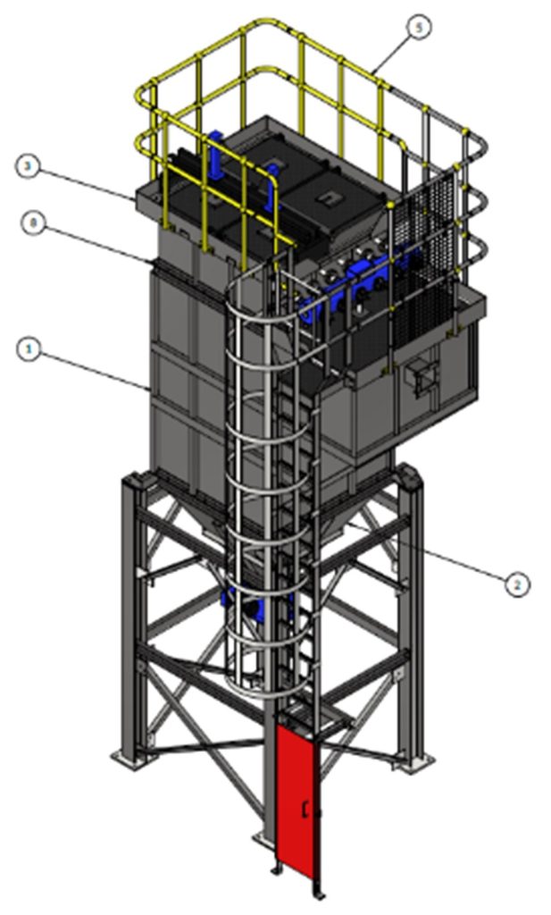
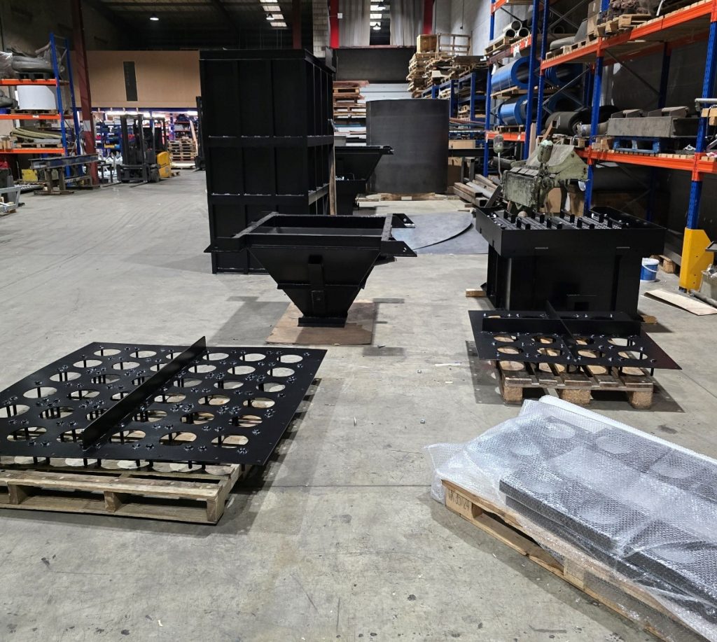
Below is the larger 6 x 6 CPCF 30 ‘Pre Heater’ filter
And smaller 4 x 4 ‘CPCF 13 Excess Air’ filter
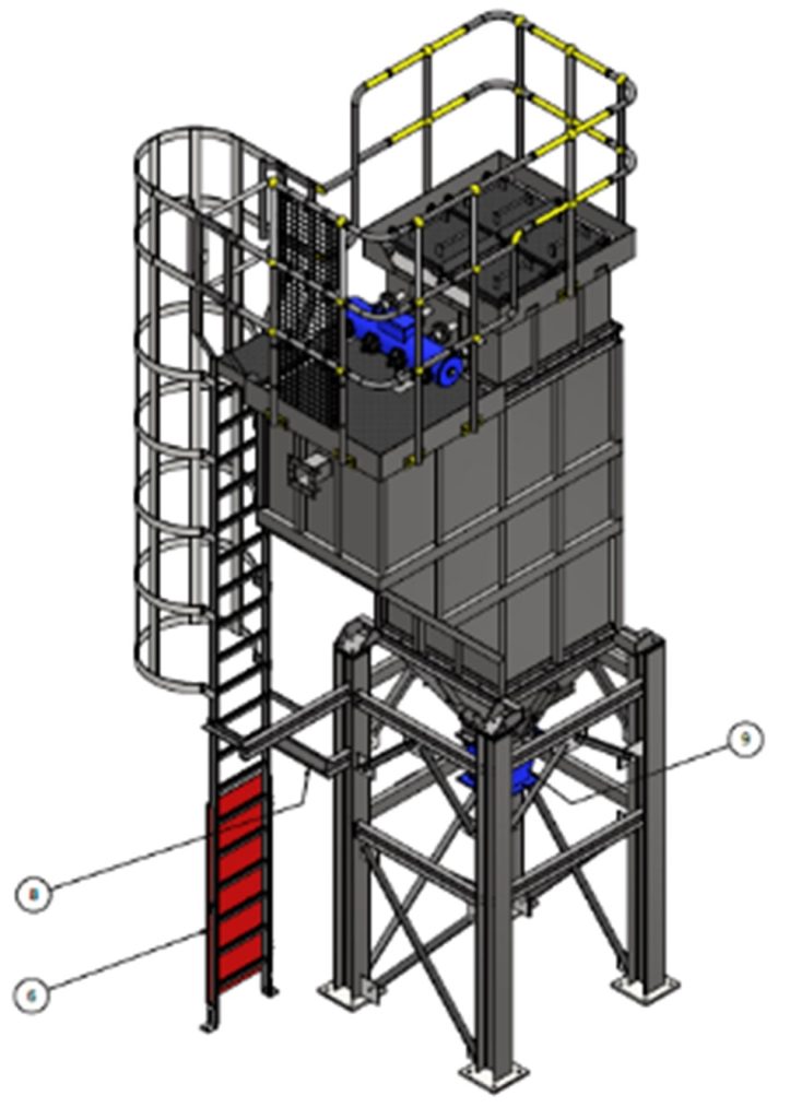
The 2 filters were designed for quite different gas volumes but both would potentially be operating in the 400-425°C range. Each of the filter consists of 3 main 4mm thick mild steel pieces, (the hopper, the body with gas inlet and at the top the clean section with gas outlet). The complete filter housing sits on top of a galvanized support frame but is isolated from the frame by placing a heat isolation pad under each corner.
The heat isolation pads act as a break to conductive heat transfer. Isolating the support structure from the hot filter steel for safety and avoid the potential for cold spots in the filter where the heat bleeds out into the support and corrosion could occur. The header tank hangs off the top section via flanges which bolt through the 40mm thick heat isolation pads which isolate the tank from the heat of the process gases. An adjustable height support sits below each tank.
On entry to the filter via the square inlet flange, the hot gasses first pass through a series of distribution plates which are CFD designed to distribute the gasses evenly across the filters and also promote downwards flow which aids the reverse jet cleaning action - CleanPULSE. The distribution section also lowers the velocity and encourages larger particles to ‘fall out’ of the gas stream directly into the hopper.
The filter body includes the inlet flange and inlet distribution section above which is an access platform where you can access/service the pulse tank and differential pressure tapping points. Under the chequer plated access floor is a series of slabs of rockwool insulation. The body is stiffened with a series of mild steel angles etc.
A mild steel Cell Plate sits between the top of the main body and the top section above. The filter elements sit in 6 rows of 6 for the larger ‘Pre-Heater’ filter and 4 rows of 4 elements for the smaller ‘Excess Air’ filter.
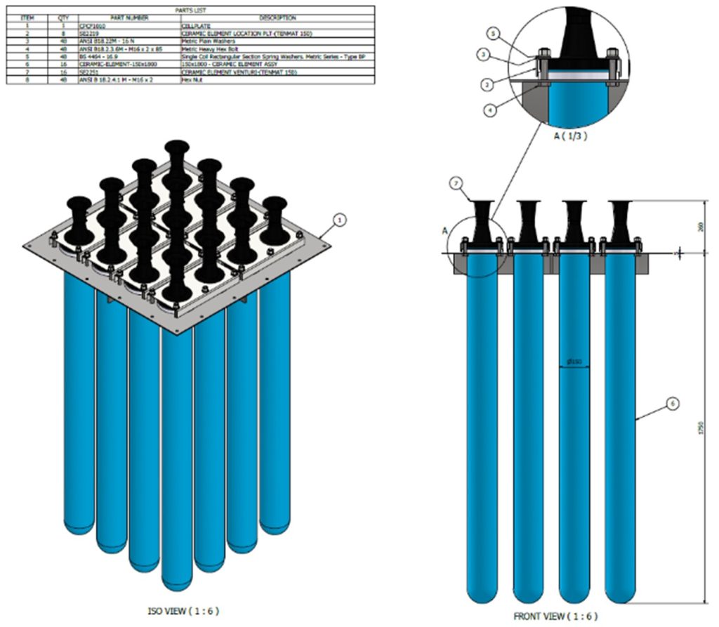
All the filter elements in both filters are off the same 1.8m length 150mm outside diameter irrespective of position in the cell plate. Both filters were designed and manufactured in accordance with EN1090 standards and certificated by the fabricators in Derbyshire.
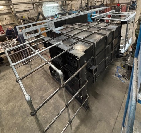
Prior to painting, a full test assembly was completed in order to ensure that when the filters arrived in Denmark we could be 100% certain they would be easily assembled by steel erectors with potentially zero previous experience of installing a filter.
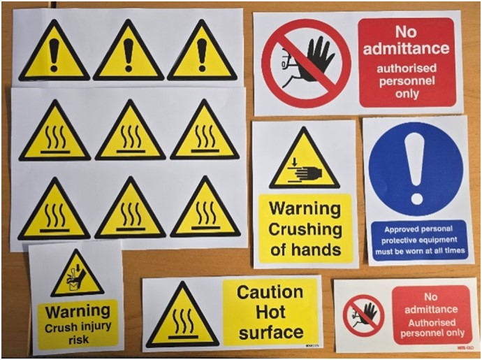
A package of safety labels was provided and details of application locations given in the installation guide, these were part of the requirement for CE Marking the filters, required by the client along with the EN1090 certification.
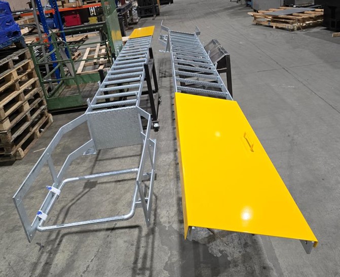
High temperature paint finish was applied to the filter fabrications following trial assembly. In this instance the filter has to be lagged and clad (on site by the client) for compliance. The handrailing, was painted, packed and labelled per filter for ease of installation on site
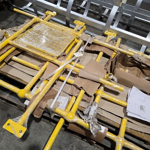
At the fabricators premises once each of the numerous pallets, boxes and fabrications was labelled, referenced according to filter, part number/drawing or the electrical component list by the project manager, the full scope of supply was collected and taken to be packed prior to transportation to Denmark which was early 2025, after some delays to starting the project by HSBC establishing bank guarantees.
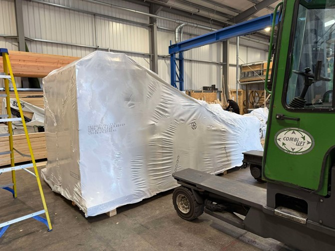
This project was delivered on time and budget to Denmark and is now in use.
Our recent Projects
An empty warehouse is always a welcome place to start a project. This is because we have a blank canvas with which to design an ideal layout for a flue gas treatment plant. Once installed, our system cleans the gases from a waste boiler and waste infeed plant and will allow the end user to stop transporting waste around the country and manage it locally, save on transport costs and produce some electricity too.
Project VC - Turnkey Flue Gas Treatment Plant for Waste Boiler
Project JP2 - Complete Flue Gas Treatment System for Intumescent Paint Furnaces (Phase 2)
Filter Designs is a trading name of Turnkey Filtration Limited, a limited liability company registered
in England under number 16279255, whose registered office is at Filtration House, Farndon Road, Market Harborough,
LE16 9NP - Website by 1PCS

